Chinese
 français
 Deutsch
 italiano
 español
 português
 Nederlands
 日本語
日本語 한국의
한국의




- Home
- >
- Battery Production Line
- >
- Pouch Cell Production Line
- >
- Unmanned Aerial Vehicle UAV Drone Battery Production Line
Categories
Hot Products


Loading...


Unmanned Aerial Vehicle UAV Drone Battery Production Line
Brand:
TOB NEW ENERGYitem no.:
TOB-UAV-PLorder(moq):
1 LinePayment:
L/C, T/Tproduct origin:
Chinashipping port:
XIAMEN
Unmanned Aerial Vehicle UAV Drone Battery Production Line Solution
Product Overview
The TOB-UAV-PL is TOB's turnkey production line solution for high-rate pouch cells used in unmanned aerial vehicles (UAVs) and drones. It covers the complete manufacturing chain from electrode processing through cell assembly, electrolyte filling, formation, and final grading — and it is delivered together with the battery materials required to run the line, so a single supplier is accountable for both the machines and the consumables.
Drone batteries are among the most performance-demanding lithium battery applications. A UAV cell must deliver three things simultaneously:
- High energy density — flight time is determined by the energy-to-weight ratio of the pack, so every gram of cell weight counts and every Wh matters.
- High discharge rate — drone motors draw high currents during takeoff, climb, and aggressive maneuvers, with sustained rates often in the 10C–30C range depending on the platform. The cell must sustain these currents without excessive voltage sag or heat build-up.
- Strict cell-to-cell consistency — drone packs are multi-cell series configurations (commonly 3S to 12S and above). A single weak cell limits pack performance and can introduce balance and safety problems, so cells must be tightly graded for capacity and internal resistance before pack assembly.
The TOB-UAV-PL is engineered around the high-rate pouch cell format, which is the dominant architecture for professional drone batteries. The pouch format uses aluminium-laminated film as the outer packaging, which is lighter than a metal can and allows the cell to be shaped to the airframe envelope. For high-rate performance, the line is configured for low-resistance cell designs — multi-tab electrode structures, thin electrodes, high-conductivity current collectors, and Z-fold stacking that provides uniform current distribution across the electrode area. Cell assembly is performed in a controlled dry environment (dew point ≤ −45 °C), electrolyte filling and degassing follow the pouch cell process route, and formation and grading are performed in-line so that each finished cell arrives at pack assembly with its performance data recorded.
TOB has supplied battery equipment and materials to the industry for over two decades. The TOB-UAV-PL is engineered, configured, and accepted as a complete production solution: scope, capacity, station parameters, site utilities, acceptance criteria, and service terms are defined in a single engineering proposal.
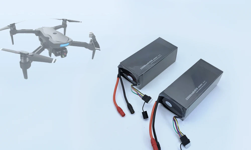
Why High-Rate Pouch Cells for UAV and Drone Batteries
- The pouch format. In a drone, weight is the enemy of flight time. A pouch cell uses thin aluminium-laminated film as its casing instead of a metal can, which reduces the weight of inactive packaging material and allows the cell to be stacked into flat, space-efficient packs. The pouch format also allows greater design freedom in cell dimensions, so the pack can be shaped to the airframe.
- The high-rate requirement. A drone's power demand is not constant. Hover requires a steady high current; takeoff, climb, and acrobatic flight demand short bursts of very high current; and descent may involve regenerative charging. The cell's internal resistance determines how much voltage drops under these loads — and voltage sag directly reduces the usable power delivered to the motors while generating heat inside the cell. Lower internal resistance means higher usable power, less heat, and longer usable flight time. For this reason, high-rate drone cells are engineered with lower electrode loading, thinner coatings, higher-conductivity current collectors, and multi-tab electrode structures that shorten the current path.
- The consistency requirement. A multi-cell drone pack behaves like a chain: the weakest cell limits the pack. If cells in a series string differ in capacity or internal resistance, the pack's usable capacity is reduced, the balancing load on the BMS increases, and the risk of over-discharge of the weakest cell rises. Tight cell-to-cell matching is therefore not an optional quality margin — it is the basis of safe, predictable drone flight. This is why the TOB-UAV-PL integrates formation, degassing, grading, and testing in the line, so every completed cell is characterised and binned before it reaches pack assembly.
- The process implication. A high-rate pouch line differs from a general-purpose pouch line in three areas: (1) the electrode section is configured for thinner, rate-optimised coatings with tight weight control (≤ ± 1.5 %); (2) the assembly section uses multi-tab or full-tab Z-fold stacking with low-resistance tab welding; and (3) grading emphasises DCIR (direct-current internal resistance) as a primary binning parameter alongside capacity. These three areas are the engineering core of the TOB-UAV-PL.
Turnkey Line Scope
The following is the standard scope of the TOB-UAV-PL solution.
| Item | Content |
| Solution | UAV / Drone high-rate pouch cell production line |
| Line scope | Electrode manufacturing section + pouch cell assembly section + formation / grading / testing section |
| Equipment | Mixer, Coater, Roller press (calender), Slitting machine, Pouch forming machine, Stacking machine, Tab welding machine, Top-side sealing machine, Electrolyte filling machine, Vacuum pre-sealing / degassing / final sealing machine, Formation machine, Battery tester |
| Materials | Cathode, Anode, Current collector, Separator, Electrolyte, Aluminium-laminated film, Tab material, etc. |
| Battery type | Pouch cell (high-rate design for UAV/drone applications) |
| Automation | Fully automatic (configuration-dependent) |
Additional dedicated stations — such as in-line burr inspection and pouch-cell secondary sealing — are integrated as required by the final cell design and are defined in the engineering proposal.
Line Process and Functional Modules
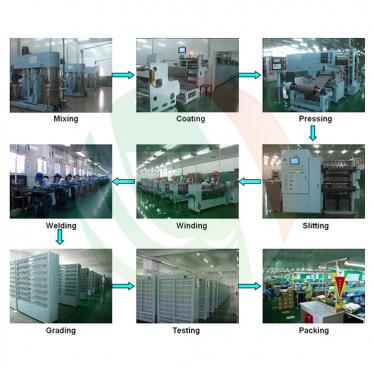
The TOB-UAV-PL is organized into three process stages, described below in process order.

Stage 1 — Electrode Manufacturing Section
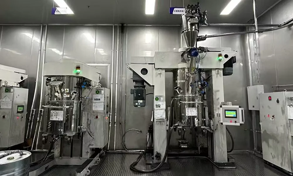
1. Mixing
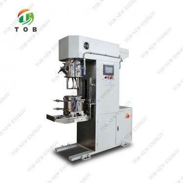
Cathode and anode slurries are prepared in dual-shaft planetary vacuum mixers at a vacuum level of ≤ −98 kPa, with viscosity controlled to ± 5 % and slurry temperature controlled to ± 2 °C. For high-rate drone cells, mixing must deliver complete dispersion of active material, conductive additive, and binder at high solid content — because the electrode formulation itself is a primary determinant of rate capability.
2. Coating
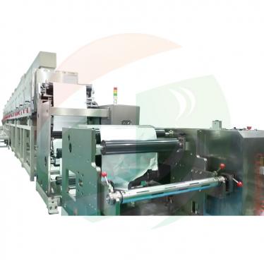
Slurries are applied to aluminium (cathode) and copper (anode) foil by slot-die coating (comma or transfer coating optional) on 400–600 mm webs at 30–60 m/min. Coating weight uniformity is held to ≤ ± 1.5 % and coating thickness accuracy to ± 2 µm, by multi-zone drying up to 130 °C. This uniformity is critical: weight variation translates directly into capacity and internal-resistance variation across the finished cells, and the grading process will bin out any cells that fall outside tolerance.
3. Calendering (Roller Press)
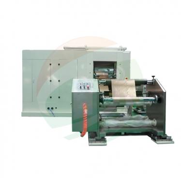
The dried electrode webs are compacted by hot calendering — the calender rollers are heated up to 120 °C — at 30–60 m/min, holding thickness accuracy to ± 1.5 µm. The density is set to balance energy density and particle contact against electrolyte access and tortuosity — a critical trade-off for high-rate electrodes.
4. Slitting
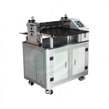
The calendered webs are slit by precision knife slitting (laser slitting optional) at 60–100 m/min, holding width accuracy to ± 0.1 mm and burr height to ≤ 5 µm (≤ 3 µm with the laser slitting option). Slit-edge quality is the first line of defence against internal short circuits — a burr that penetrates the separator during stacking or cycling can cause a short inside a flight pack.
5. Electrode Burr Inspection (In-Line)
The slit edges are verified in-line by high-magnification vision inspection at 40–500× with a measurement resolution of ≤ 1 µm, providing process feedback to the slitting station and preventing burr-related short circuits downstream.
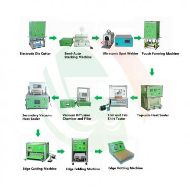
Stage 2 — Pouch Cell Assembly Section
6. Pouch Forming (Aluminium-Laminated Film)
The aluminium-laminated film (90–152 µm) is formed into a pocket of the required geometry, with pocket depth up to 10 mm and depth accuracy of ± 0.05 mm, at a forming speed of ≥ 25 PPM. The pocket must be formed without wrinkles, pinholes, or damage to the inner PP sealing layer, because these defects become leakage paths in the finished cell.
7. Stacking (Z-Fold)
The cathode, separator, and anode are assembled into the electrode stack by Z-fold stacking with a stacking accuracy of ± 0.2 mm, a cycle time of ≤ 0.3 s/layer, and servo constant-tension separator control within ± 5 %. Up to 100 layers are stacked depending on the cell design. Z-fold stacking produces a flat stack with uniform current distribution, reducing local current density and improving rate capability.
8. Tab Welding
The electrode tabs are welded by ultrasonic welding (Cu/Al) with a weld strength of ≥ 25 N (sample destructive test) and 100 % in-process weld quality monitoring. For high-rate drone cells the tab is the critical current path: a high-resistance weld raises the cell's total internal resistance and creates a local hot spot under high-rate discharge.
9. Pouch Insertion and Top-Side Sealing
The finished electrode stack is inserted into the formed pouch pocket; top-side (tab-side) sealing is performed at 170–200 °C, 0.3–0.6 MPa, with a 2–5 s dwell time, holding seal width accuracy to ± 0.1 mm and seal strength to ≥ 40 N/15 mm, using the appropriate sealant film around the tabs to ensure leak-tightness.
10. Electrolyte Filling
Electrolyte is introduced under vacuum (≤ −90 kPa) with fill accuracy of ± 0.5 % and a cycle time of 20–45 s depending on format. Accurate fill volume control directly affects capacity and cycle-life consistency, and full wetting of the rate-optimised electrode stack is essential for delivering the cell's rated performance.
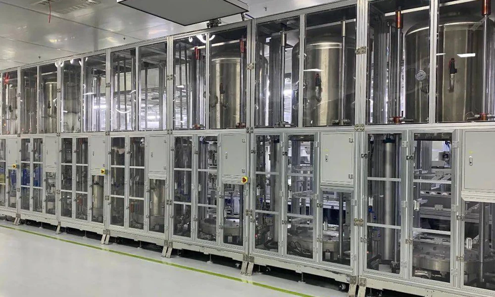
11. Vacuum Pre-Sealing, Degassing, and Final Sealing
After filling and formation-induced gas generation, the cell undergoes degassing at ≤ −90 kPa: the pouch is opened under vacuum, the gas is removed, and the cell is re-sealed. The final seal is verified against a helium leak-rate criterion of ≤ 1 × 10⁻⁶ Pa·m³/s. Residual gas would create swelling, reduce electrode contact, and degrade performance over life — making this station critical for pouch cell reliability.
Stage 3 — Formation, Grading, and Testing Section
12. Formation
The filled cells undergo controlled first charge-discharge cycles to form the SEI. Formation and grading are performed on 256-channel cabinets (512-channel optional) with current accuracy of ± 0.05 % FS + 0.05 % RD, voltage accuracy of ≤ ± 2 mV, and an energy-feedback efficiency above 65 % at rated conditions. For high-rate drone cells, formation parameters are tuned to build a stable, low-resistance interface.
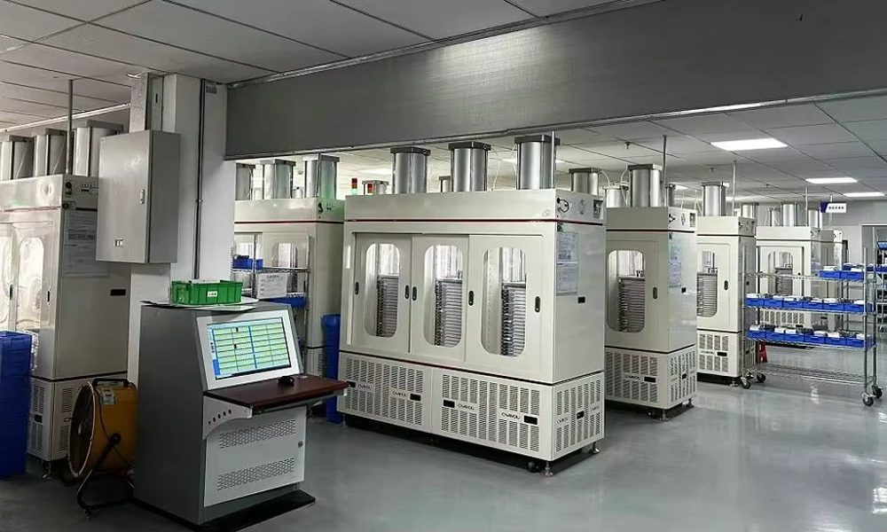
13. Grading and Testing
Each finished cell is capacity-graded and its DCIR (direct-current internal resistance) — measured by the pulse-current method — together with ACIR and OCV, is recorded; cells are sorted into 10 or more bins, with DCIR treated as a primary binning parameter for these high-rate drone cells. The grading system outputs the per-cell data needed for traceability and for downstream pack matching.
Station Parameter Specifications
The following table specifies the station parameters fixed for the TOB-UAV-PL at the engineering-proposal stage, according to the selected cell design and line configuration.
| Process Section | Station | Parameter | Value |
| Electrode | Mixing | Mixer type | Dual-shaft planetary vacuum mixer |
| Vacuum level | ≤ −98 kPa | ||
| Viscosity control tolerance | ± 5 % | ||
| Slurry temperature control | ± 2 °C | ||
| Coating | Coating method | Slot die (comma / transfer optional) | |
| Web width range | 400–600 mm | ||
| Coating speed | 30–60 m/min (process dependent) | ||
| Coating weight uniformity | ≤ ± 1.5 % | ||
| Coating thickness accuracy | ± 2 µm | ||
| Drying temperature | Up to 130 °C, multi-zone | ||
| Calendering | Roll heating | Hot calendering, up to 120 °C | |
| Speed | 30–60 m/min | ||
| Thickness accuracy | ± 1.5 µm | ||
| Slitting | Method | Precision knife slitting (laser slitting optional) | |
| Speed | 60–100 m/min | ||
| Width accuracy | ± 0.1 mm | ||
| Burr height control | ≤ 5 µm (≤ 3 µm with laser slitting option) | ||
| Burr Inspection | Method | In-line high-magnification vision inspection | |
| Measurement resolution | ≤ 1 µm | ||
| Magnification | 40–500× | ||
| Assembly | Pouch Forming | Film thickness range | 90–152 µm |
| Pocket depth | Up to 10 mm (cell design dependent) | ||
| Depth accuracy | ± 0.05 mm | ||
| Forming speed | ≥ 25 PPM | ||
| Stacking (Z-Fold) | Stacking accuracy | ± 0.2 mm | |
| Cycle time | ≤ 0.3 s/layer | ||
| Separator tension control | Servo constant tension, ± 5 % | ||
| Max. layers | Up to 100 (design dependent) | ||
| Tab Welding | Method | Ultrasonic welding (Cu / Al) | |
| Weld strength | ≥ 25 N pull (sample destructive test) | ||
| Weld quality monitoring | 100 % in-process | ||
| Top-Side Sealing | Temperature | 170–200 °C | |
| Pressure | 0.3–0.6 MPa | ||
| Dwell time | 2–5 s | ||
| Seal width accuracy | ± 0.1 mm | ||
| Seal strength | ≥ 40 N / 15 mm | ||
| Electrolyte Filling | Fill accuracy | ± 0.5 % | |
| Vacuum level | ≤ −90 kPa | ||
| Cycle time | 20–45 s (format dependent) | ||
| Degassing / Final Sealing | Vacuum level | ≤ −90 kPa | |
| Leak rate criterion (helium) | ≤ 1 × 10⁻⁶ Pa·m³/s | ||
| Formation / Grading | Formation & Grading | Cabinet channels | 256 / cabinet (512 optional) |
| Current accuracy | ± 0.05 % FS + 0.05 % RD | ||
| Voltage accuracy | ≤ ± 2 mV | ||
| Energy feedback efficiency | > 65 % (rated conditions) | ||
| Grading / Test | Battery Testing | Test parameters | Capacity, DCIR, ACIR, OCV |
| DCIR method | Pulse current method | ||
| Grading | ≥ 10 bins; DCIR as primary binning parameter |
Site Utilities and Facility Requirements
A pouch cell production line requires a controlled manufacturing environment, particularly in the assembly section where moisture-sensitive materials are processed. The following utility and facility requirements apply.
| Item | Requirement |
| Power supply | 380 V / 3-phase / 50 Hz (± 5 %); alternate voltages per destination. Total installed power: reference 0.6–1.2 MW (configuration dependent) |
| Compressed air | 0.6–0.8 MPa; oil-free and dry per ISO 8573-1, pressure dew point ≤ −40 °C; reference total consumption 5–10 m³/h |
| Nitrogen | Purity ≥ 99.999 %; 0.4–0.6 MPa; reference total consumption 10–30 m³/h (process + dry-room usage) |
| Vacuum | Process vacuum ≤ −90 kPa (per-station pumps, or facility vacuum supply) |
| Cooling | Chilled water 12–18 °C for process equipment; formation modules cooled per configuration |
| Dry room (assembly section) | Dew point ≤ −45 °C; temperature 25 ± 3 °C |
| Cleanliness | ISO Class 8 (Class 100,000) general area; ISO Class 7 (Class 10,000) at critical stations |
| Building | Reference area 1,500–3,000 m² (incl. material storage and formation area); clear height ≥ 4.0 m; floor loading ≥ 800 kg/m² in equipment areas |
| Exhaust & environment | Solvent exhaust and NMP recovery per local environmental regulations; exhaust volume per oven design |
| Logistics | Material flow, aisle width, and handling interfaces per layout drawing |
A site-preparation guide is provided to the customer during project planning.
Capacity, Yield, and Reliability Targets
Production targets for the TOB-UAV-PL are defined in the equipment technical agreement. The table below shows the committed framework.
| Item | Value |
| Assembly section output | 5–15 cells/min (format dependent; nominal design 10 PPM) |
| Annual design output | Reference 2–5 million cells/year ≈ 0.05–0.2 GWh/year equivalent (cell-format dependent) |
| Electrode section | Sized to match assembly-section consumption |
| OEE | ≥ 85 % steady-state target |
| Yield — electrode section | ≥ 98.5 % |
| Yield — assembly section | ≥ 99.0 % |
| Yield — formation / grading pass | ≥ 99.0 % |
| Composite line yield | ≥ 96.5 % (acceptance basis); ≥ 97.5 % mature steady-state target |
| MTBF / MTTR | MTBF ≥ 24 h; MTTR ≤ 30 min (line level, weekly calculation basis) |
| Energy feedback (formation/grading) | > 65 % at rated conditions |
All committed values are fixed in the equipment technical agreement before contract signature.
Project Delivery: Timeline, FAT / SAT, and Acceptance
A production line is delivered as a project with defined milestones. The schedule below follows TOB's standard project process and is confirmed in the contract.
| Phase | Duration |
| Engineering & design (incl. 3D design review) | 6–10 weeks |
| Manufacturing | 16–24 weeks |
| Factory pre-acceptance (FAT) | 2–4 weeks |
| Shipping | 3–6 weeks |
| On-site installation & commissioning | 6–10 weeks; team of 6–12 TOB engineers |
| Trial production & process optimization | 4–8 weeks |
| Formal acceptance | Initiated after 4 weeks of continuous production meeting the technical targets |
| Overall (order → formal acceptance) | Typically 10–14 months |
Acceptance framework: Acceptance is performed against the equipment technical agreement, the FAT checklist, and TOB's standard project acceptance requirements (TPM requirements, 5S acceptance, general EHS requirements, and TECSA requirements). Formal acceptance is initiated after the line has operated continuously and met the specified technical indicators; the acceptance result takes effect upon signature by both parties. A warranty acceptance review is conducted based on the operational status of the month preceding warranty expiration.
Service, Warranty, and Training
| Item | Terms |
| Warranty | 12 months from formal acceptance (standard); covers repair, maintenance, and parts, excluding consumables; extended terms per contract |
| Response time | ≤ 2 hours response; remote diagnostics as standard; on-site support scheduled per contract |
| After warranty | Continued repair/maintenance support; labour and transport at reasonable cost; parts at cost |
| Training | Included: operation, maintenance, fault analysis and troubleshooting, safety, and emergency handling; duration per project plan |
| Documentation | Certificate of conformity, operation manual, maintenance manual, general assembly drawing, pneumatic/electrical schematics, and spare-parts list — electronic + paper |
Intelligence, Data Traceability, and MES Integration
Modern drone battery factories require cell-level traceability and process-data integration, because the performance consistency of the pack depends on the identity and measured characteristics of every cell. The TOB-UAV-PL supports the following capabilities on configuration:
- Cell-level traceability: Barcode / QR binding at cell level, with process and test data linked to each cell identity, supporting forward and backward traceability and pack-matching workflows.
- MES / SCADA integration: Data upload via industry-standard interfaces (e.g., Web/API) for integration with the factory MES; interface specification defined during project engineering.
- Process data management: Recipe management, measurement-result logging, alarm and event history, and statistical process analysis (SPC).
- Formation / grading data: Per-channel charge-discharge curves, capacity grading results, and internal-resistance (DCIR/ACIR) data, with export formats for analysis and archiving.
- Energy monitoring: Recording of charge/discharge energy and energy-feedback data from the formation and grading section.
The final data-integration scope is defined with the customer's IT/MES requirements during project planning.
Battery Materials Supplied with the Line
TOB supplies the battery materials required to run the TOB-UAV-PL, so that process and material are co-optimised and the customer has a single accountable supplier for both.
| Material | Role in the High-Rate Pouch Cell |
| Cathode material | Cathode active materials for the high-rate, high-energy positive electrode |
| Anode material | Anode active materials for the negative electrode |
| Current collector | Aluminium foil (cathode) and copper foil (anode), selected for high-rate current paths |
| Separator | Thin separator membrane engineered for uniform ionic transport and safety in the drone cell |
| Electrolyte | Electrolyte formulation matched to the cell chemistry and designed for high-rate performance |
| Aluminium-laminated film | Pouch packaging film for the cell enclosure |
| Tab material | Tab leads for high-rate current transfer from the electrode stack to the external circuit |
Engineering & Business FAQ
Q1: Why are pouch cells used for drone batteries, and why does this line focus on high-rate design?
Pouch cells use lightweight aluminium-laminated film instead of a metal can, which reduces packaging weight and maximises the energy-to-weight ratio that determines flight time. They can also be formed into flat, space-efficient shapes. Drone motors draw high currents during takeoff, climb, and aggressive maneuvers, so the cell design is optimised for high discharge rate: lower electrode loading, thin coatings, high-conductivity current collectors, and multi-tab structures that shorten the current path and reduce internal resistance. The TOB-UAV-PL is configured for this high-rate pouch cell architecture.
Q2: What assembly process does the line use — stacking or winding?
The line uses Z-fold stacking as the standard assembly route for high-rate drone cells, with a stacking accuracy of ± 0.2 mm and a cycle time of ≤ 0.3 s/layer. The flat stacked construction provides uniform current distribution and lower local current density than wound construction. Winding can also be configured when the cell design requires it; the assembly process is fixed according to the cell design specified at order.
Q3: What is the scope of the TOB-UAV-PL?
The scope covers the electrode manufacturing section (mixing, coating, calendering, slitting, and in-line burr inspection), the pouch cell assembly section (pouch forming, Z-fold stacking, tab welding, top-side sealing, electrolyte filling, vacuum pre-sealing, degassing, and final sealing), and the formation / grading / testing section. The matching battery materials — including the aluminium-laminated film — are supplied with the line.
Q4: What capacity can the line be configured for?
The line is engineered to the buyer's target output. A typical configuration is designed for 5–15 cells per minute at the assembly section (nominal design 10 PPM), corresponding to a reference annual output of 2–5 million cells (approximately 0.05–0.2 GWh/year equivalent, cell-format dependent). Because drone cells vary widely in size, the committed capacity is fixed in the engineering proposal according to the specific cell design.
Q5: What site conditions must be prepared before installation?
The line requires 380 V three-phase power with a total installed capacity in the reference range of 0.6–1.2 MW, compressed air (0.6–0.8 MPa, oil-free, dew point ≤ −40 °C), nitrogen at ≥ 99.999 % purity, process vacuum ≤ −90 kPa, and chilled water at 12–18 °C. Critically for pouch cell assembly, a dry room with a dew point ≤ −45 °C and temperature of 25 ± 3 °C is required. A site-preparation guide covering all utility, building, and logistics requirements is provided during project planning.
Q6: How is the project delivered and accepted?
The project follows a defined sequence: engineering and design (6–10 weeks), manufacturing (16–24 weeks), factory pre-acceptance (2–4 weeks), shipping (3–6 weeks), on-site installation and commissioning (6–10 weeks, with a team of 6–12 TOB engineers), trial production and process optimization (4–8 weeks), and formal acceptance. Overall delivery from order to formal acceptance is typically 10–14 months. Acceptance is against the equipment technical agreement and TOB's standard acceptance framework (FAT checklist, TPM requirements, 5S acceptance, EHS, and TECSA requirements).
Q7: What are the warranty and service terms?
The standard warranty is 12 months from formal acceptance, covering repair, maintenance, and replacement of components (excluding consumables). After-sales service responds within 2 hours of notification, with remote diagnostics as standard. Training for operation, maintenance, and troubleshooting is provided, and the full documentation package — including operation and maintenance manuals and assembly drawings — is delivered with the line.
Q8: How does the line ensure that finished cells are consistent enough for drone packs?
Formation, degassing, grading, and testing are integrated in-line, so every cell is formed under identical conditions and then measured for capacity and DCIR (direct-current internal resistance) using the pulse-current method. Cells are sorted into 10 or more bins, with DCIR treated as a primary binning parameter for high-rate drone applications. The composite line yield target is ≥ 96.5 % on acceptance, with a mature steady-state target of ≥ 97.5 %.
Q9: Can TOB supply the battery materials as well as the machinery?
Yes. TOB supplies the cathode material, anode material, current collector foils, separator, electrolyte, aluminium-laminated film, and tab material alongside the production line, so that process and material are co-optimised and the customer has a single supplier accountable for both.
Q10: What certifications apply?
TOB operates certified management systems (ISO 9001, IATF 16949, ISO 14001, ISO 45001). Equipment certification, including CE marking, is arranged according to the destination market and the customer's compliance list; the specific certification scope for the line is confirmed in the contract.
Ready to plan a high-rate pouch cell factory for UAV and drone batteries? Contact TOB's pouch cell line engineers with your target cell capacity, discharge rate, and required annual output. We will provide a line-scope proposal covering equipment, matching battery materials, site utilities, acceptance criteria, and project timeline.
tob.amy@tobmachine.com | +86 181 2071 5609
You May Also Need
▶ 4680 / 4690 Tabless Cylindrical Cell Production Line (TOB-4680PL) — The large-format tabless cylindrical cell line from the same TOB turnkey platform. Where the TOB-UAV-PL builds high-rate pouch cells for airborne platforms, the TOB-4680PL builds 46 mm-diameter tabless cylindrical cells for EV, energy-storage, and high-power industrial applications — offering manufacturers a second cell format built on the same engineering and acceptance framework.
▶ 21700 Tabless Cylindrical Battery Production Line — The smaller-format tabless cylindrical line, also fully automatic with in-line formation and grading. Complements the TOB-UAV-PL by covering the cylindrical cell route, giving drone and UAV battery manufacturers the option to compare or combine pouch and small-cylindrical formats within one production strategy.
▶ Drone Battery Pilot Line — A pilot-scale drone battery production line for cell development, process validation, and small-batch manufacturing. Ideally paired with the TOB-UAV-PL: prove the cell design, process window, and formation protocol on the pilot line first, then scale to the full TOB-UAV-PL production solution with validated parameters and reduced ramp-up risk.
Previous:
Drone Battery Pilot LineNext:
Pouch Cell Assembly Line
If you are interested in our products and want to know more details,please leave a message here,we will reply you as soon as we can.

 subscribe to us